Sometimes when using a BOG in both directions it requires to disconnect the termination resistor. This now can be done from the shack. The modification is quite easy and only affects the BOG terminiation side and the shacks side. Antenna, transformer and feedline are not changed. Also no DC path is needed between Rx and antenna and the existing isolation is being preserved.
If this is not enough and you want to turn your BOG into a dual-feed then look here.
|
|
|
|
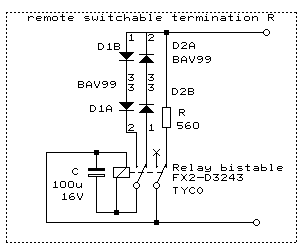
This replaces the usual termination resistor at the far end of a BOG and allows to turn on/off the termination resistor remote controlled.
Nothing else has to be modified on the BOG setup as it works by an AC pulse in the 50..150kHz range and it goes across the impedance transformer. The return path is ground, so no need for an extra wire. No permanent current will flow and thus avoiding problems with electrolytic effects on the ground rods The bistable relay needs a brief pulse to be switched, and then changes polarity and would immediately switch back if the AC signal would stay for a longer time. The diodes in series disconnect the relay coil path for voltages below 1.4V so that RF signals are not being attenuated. They just present a very small capacitor that can be ignored for MW frequencies | ||||||||||
|
|
To generate a pulse on the PC COM2: Call this in the DOS window:
|
|
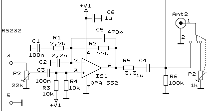
This circuit in my phaser unit controls the relay at the BOG far side.
P2 is the RF attenuator and when set to zero position its switch connects the antenna feedline to the OpAmp output that generates an AC pulse. Amplitude and duration depends on the ground resistance between far and near side of the BOG. You have to adjust both for your setup. I used V1= 15V and 100 msec duration. As a pulse generator I used the RS232 Tx signal of my PC COM-port that transmits a string of 'U' at 115200 Baud. That allows for easy pulse length changes, but you can use a simple 555 timer setup instead. Because P2 only connects the AC pulse when set to zero position, the current pulse cannot harm the receiver input. Depending on which pot is turned to zero, the relay of either Feed-1 or Feed-2 is being switched. |