TV-Card modifications


Watch this video to see the result of free-run mode and narrow IF-bandwidth, note how weak signals still delivers video.

My TV card is a FlyVideo 3000 (photo) based on the SAA 7134 chip. The Philips designed tuner frontend contains the mixer TDA 5737 and IF / synchronous demodulator TDA 9809. It is very sensitive, I was surprised that its video carrier PLL already locks on signal levels (1uV) that just became audible on a scanner. But besides a darker going screen nothing else is yet visible, because it requires a lot more strenght before the picture synchronizes. Also a few interferences easily kicks it out of sync. Further the built-in SAW IF filter is pretty wide.
On the other hand a TV card has a lot of potential when combined with video improvement processing that is freely available for the PC. This requires a stable picture position so that consecutive frames can effectively be averaged. It is achieved by ignoring the transmitted sync pulses and switching the card into free run mode. Why would you want to receive sync pulses when you already know what they are? By slightly pulling the crystal frequency a picture standstill is achieved. Now a picture already appears at very low signal strengths, namely at the moment when the video carrier PLL does lock. Winradio (which is supposed to be calibrated) measures 1..3uV input level ( = S3). The adaptive noise filter removes a lot of noise and the picture becomes earlier recognizable. This represents several dB antenna gain.

I designed a variable bandwith IF filter. Using a weak signal I compared a narrow bandwith video without adaptive noise filter against a wide bandwith but with turned-on noise filter. The noise supression was similar, the noise filter was even a bit better and preserved more picture resolution which the narrow bandwith version never can do. So why using a narrow IF bandwith at all? It helps reducing interferences that fall within the spectrum or come from adjacent channels. A noise filter cannot do that. Also it helps the carrier-PLL to lock earlier on weak signals.

Other problems
During production the female cinch antenna connector is pushed through the metal box from the inside and looks pretty solid. But RF wise the connection is lousy. In my case the coax cable shield picked up weak signals while the cable was terminated with 50 ohms without any connected antenna. It took me a while to figure out what was wrong. The earlier models have this soldered, later models don't, probably to save costs.

How to fix it: Open the tuner metal box and solder the cinch connector with the metall frame.


Receiving picture in unlocked mode  

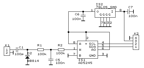
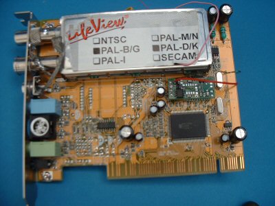
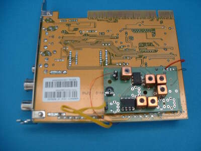
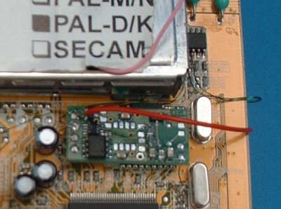
The TV card can be switched to free running mode. Transmitted H-Sync and V-Sync are ignored and an orthognal picture appears that slowly moves horizontally but cannot collapse anymore. The speed of movement depends on the TV-card's crystal oscillator. Its frequency can be adjusted slighty so that the picture gets to a near standstill. For this a 10pF capacitor-trimmer needs to be soldered from ground to the 24.576 MHz crystal (photo) , and adjust it to a picture standstill. This is temperature dependend so you may still get slight movement later on. A more elegant solution is a circuit that allows to precisely adjust the standstill with a mouse movement, see below.

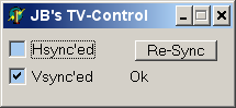
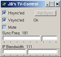
For switching free running mode on/off I created a small program that only works with TV-cards containing the SAA713x chip. When free running, a click on Re-Sync will for 1 second turn on synchronisation. Click on it at the moment when the TV signal is good, so that the picture can re-align properly on the screen.
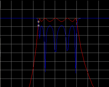
In free-run you can even see a picture during strong interferences or very weak reception when using simultanously the Noise Reduction Adaptive Filter

Installation: unzip all files into one directory and start TVcontrol.exe


The elegant solution  


This circuit allows to interactively adjust picture movement to a stand still, It replaces the above mentioned trimmer.
First remove the original 22pF capacitor at the 24,576Mhz crystal pin on the TV card. In free run the picture now should move to the right. Connect K1 #1 to the removed capacitor pad.
Connect K2 pin
4 to ground
3 to +12V
2 to pin 6 of the 8-pin eeprom near the tuner
1 to pin 5 of the 8-pin eeprom near the tuner

See how it is mounted on the TV-card

Now you can adjust the picture position and horizontal movement with the mouse.


Variable Bandwith TV- IF filter  

Allows to continously adjust the bandwith of the video IF-filter from 0.3 to 6 Mhz
It is based on the idea of IF Bandpass filtering of AM TV signals
, however it does not preserve audio carrier or color when its bandwith is reduced. It is mainly used for TV-DX and the sound can still be received with a separate receiver. However when set to wide bandwith, sound & color are passed through. Further, instead of predefined bandwiths its bandwith is continously adjustable from 0.3 ..6 MHz, but values below 500kHz don't really make sense.
This filter is inserted between SAW filter and the mixer (TDA 5737) differential outputs pin 11,12 which are low impedance and aren't affected by a small cable leading to the K1 input of my filter. The orginal copper tracks to the SAW filter are cut and are now connected to the K2 output of my filter. This is a tricky process, space inside the tuner is very tiny.

The IIC (SCL, SDA) control lines of the filter are connected to the IIC pins of the SAA7134, so that it can be comfortably controlled by the above windows program. The +12V supply is alos taken from the card.


Simulation

Start/Stop: 5 - 25 MHz (2MHz/div) Marker= 12 MHz
Y: 10dB/div


Measured Response

Marker= 12 MHz

variable bandwith TV- IF circuit  


This filter was designed for a higher order, I initially left out: C4,5,6 & L5,6 and found performance suffcient. I never tried the the full version.

Note: you need test equipment to align the filter, you are lost without it.


Sync-Adjust board mounted on top side


variable BW IF board mounted on bottom side


Detailed View


most simple for free run mode: a variable capacitor


Sensitivity Demo Video
This video shows my screen taken via a camera in order to show both TV-screen and desktop.
1TV from Ryazan Russia comes in at varying strength. Winradio simultanously shows the strength on its S-meter. See how it gets down to the 1..2uV range while the video still remains recognizable. The bandwidth is set to narrow. During stronger levels I increase the bandwidth via the right slider of my TV-Control on top of the TV window. The left part is used for picture position control. Free-run mode is turned on.

Pay attention to Winradio's S-meter, not the spectrum to see the real level changes.
Note: the video is silent, as there was no audio

This webm-format video will not show on IE as it ignores the webm-specification. Please use another browser.


  ©  3S design GmbH   Zeiterfassungs-Systeme   Zugangskontrolle-Systeme   BDE-Systeme   Ferienwohnung südliche Nordsee