Dual-Feed EWE or BOG

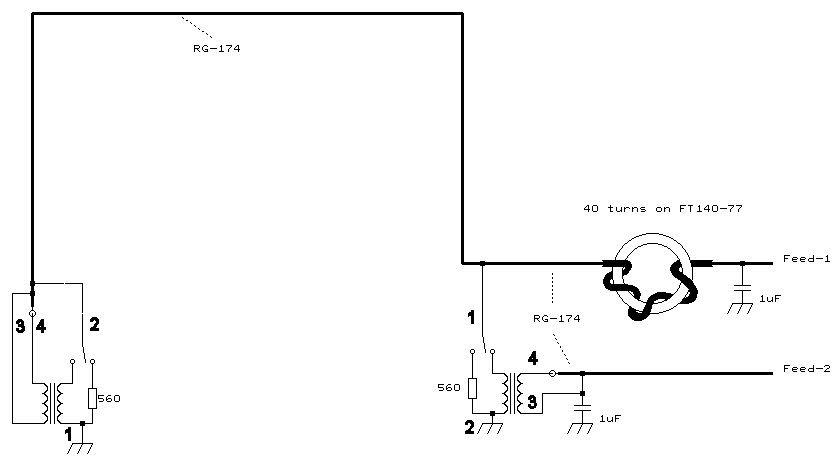
Block circuit showing the principal setup

This whole idea came about when I had to run a RG174 feed cable to the EWE feed that was further away from the house than the termination side. So why can't I use the feed cable screen as the antenna itself and saving one wire?

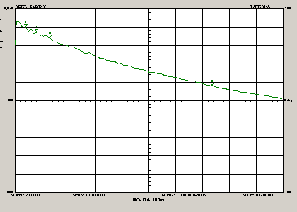
Well, I can and it's rather easy to achieve. The key component is the RF blocker that isolates the sides of antenna and feed line going to the house. It is a FT140-77 torroid on which is wounded as many turns of RG174 as possible. 40 turns in my case. This represents about 22k-Ohm @ 1MHz, enough for an efficient RF barrier. Even for 100 kHz it is 2200 Ohm.
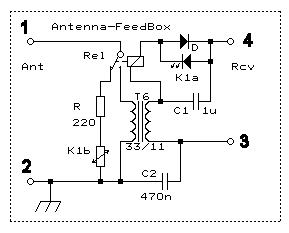
Now assume both switches are set to the left side. The EWE far side transformer secondary feeds Feed-1. At the near side the RG174-screen is connected to the termination resistor completing the EWE structure.
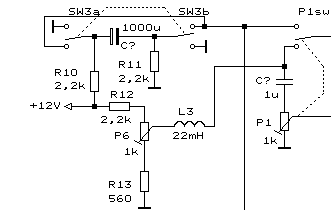
Flipping both switches to the right side and you get signals from the opposite direction on Feed-2. Setting each switch to the transformer side and you get front and back signal simultanously on Feed-1 & Feed-2. These can be used for phasing. Make sure that Feed-1/2 is terminated with 50 Ohms all the time, because it translates to about 450 Ohms and is needed by the EWE instead of the usual 560 Ohm resistor to keep its directivity.

Using both signals of the same antenna for nulling is amazing. The phaser is a lot easier to adjust and often needs no phase shift. Just add or subtract both signals, adjust the magnitude and the unwanted it gone, that works down to LW. I could cancel out BBC-198 amd hear Poland, cancel DLF-153 and hear Yunost (Taldom), cancel Kaliningrad-1215 and hear Virgin. For lack of MW TA signals I went to the tropical band. Switching to one side you hear on 49xx kHz China, while the other end of the same antenna gave Brasil.

Circuit Details  


The switches are actually bistable relays that are controlled from my phaser box. The resistor is a variable remote controlled one. Both sit in the feedbox.
The bistable relay only needs a short positive or negative pulse of 10mA to be switched.
Only 0..1mA is needed to adjust the optocoupler controlled resistor K1 (NSL-32SR3 by Silonex), this current flows also via the relay but is too small to have any effect on it.
Diode D provides the negative current path needed for the relay pulse. T6 is a FT50-77


Phaser unit side


P1 is the RF attenuator and P6 remote controls the termination resistor K1 in the feedbox.
P1 endpoint switch P1sw connects the feedline to SW3 which is a three position switch remaining in the center when untouched. Capacitor 1000uF can thus be charged. Pushing SW3 in either direction will discharge it generating a positive or negative current pulse that switches the relay to the appropiate position. Because P1sw only connects SW3 when P1 is set to zero position, the current pulse cannot harm the input of the receiver. Depending on which pot is turned to zero, the relay of either Feed-1 or Feed-2 is being switched.

Advantages:
·Two antennas for the price of one  
·Antenna farm can be reduced by half  
·Very effective nulling possible even down to LW  
·Feedlines are only needed to the side closest to the house  
·Cattle can run beneath an EWE as no feed line runs on the ground  


Loss of 100m RG174 cable


Vert: 2dB/Div Horiz: 200..10200kHz 1MHz/Div

Dual feed BOG  
 
This dual feed structure also works great with a beverage antenna. I built a 100m BOG using RG174 since I only could get 100m rolls of RG174 cable. Longer version can be made, however note that 100m RG174 loss is 3.2dB @ 1500kHz. Using 300m would result in 10dB loss


  ©  3S design GmbH   Zeiterfassungs-Systeme   Zugangskontrolle-Systeme   BDE-Systeme   Ferienwohnung südliche Nordsee